


Introduction
Trigeminal neuralgia (TN) presents a sudden severe, electric shock like, stabbing, and recurrent facial pain involving one or more of the trigeminal nerve divisions. TN is the most common among cranial neuralgia. The severe and disabling pain nature of TN significantly affects the quality of life and may result in psychologic distress and even lead to suicide [1-3].
Radiofrequency thermocoagulation (RFT), glycerol injections, and balloon compressions of the gasserian ganglion through the foramen ovale (FO) have been proven to be effective TN therapeutic interventions following conservative care failure [4,5]. However, the use of these intervention is limited by unclear visualization of FO, which may results in various complications including mispuncture of the jugular foramen, foramen lacerum, inferior orbital fissure, or foramen spinosum, and even damage to the internal carotid artery [6].
Clear identification of the FO is the most important initial step for a successful percutaneous procedures of TN. However, accessing the FO with C-arm guidance is very challenging even for experienced pain physician. A recent study suggested the H-figure landmark to easily identify the FO [7]. According to their study, the two vertical lines of the H-figure are the medial border of the mandible and the lateral edge of the maxilla, and the superior line of petrous ridge of temporal bone as the horizontal line. In addition, they suggested that the medial end of the temporomandibular joint (TMJ) is a very useful fluoroscopic landmark to identify the superior line of the petrous ridge of temporal bone and to aid in optimizing the FO view [7]. When the medial end of the TMJ is located within the mandibular notch (located between the medial and lateral border of the mandibular ramus), the FO is positioned very close to the midpoint of the H-figure. [7]. Previous study also demonstrated that the mandibular angle and the occipital cortex line as anatomic landmarks to facilitate the FO visualization [8].
For the successful percutaneous procedures using trans-oval method, the FO should be the most central point with maximum visualization. Proper axial and lateral oblique angulation of the C-arm is essential to better visualize the FO within the H-figure. However, so far, no study has demonstrated practical fluoroscopic landmark for the proper angulation of C-arm for better visualization of FO during RFT of TN.
The purpose of this study was to verify whether the medial end of the temporomandibular joint and the distance between the mandibular angle and the occipital inner line can be used as fluoroscopic landmark to determine the proper angulation of the C-arm.
Methods
Patients
This study was performed in a retrospective manner after approval of our institutional review board (2021-06-025). Patients of TN who had received a RFT from May 2019 to May 2021 were included. Diagnosis of TN was performed according to the criteria of the International Classification of Headache Disorder-III (2018) [9]. Patients who did not have successful outcome after fluoroscopic guided RFT and patients whose fluoroscopic images did not include the medial end of TMJ or mandibular angle and occipital inner line were excluded.
Identification and analysis of TN patients who had received a RFT were performed using a program of Clinical Data Warehouse v 2.5 (CDW, Planit Healthcare, Seoul, Korea). The search word that we used with the CDW for analysis was “radiofrequency thermocoagulation of gasserian ganglion”.
RFT procedure
Informed consent was obtained from patients before the procedure of RFT.
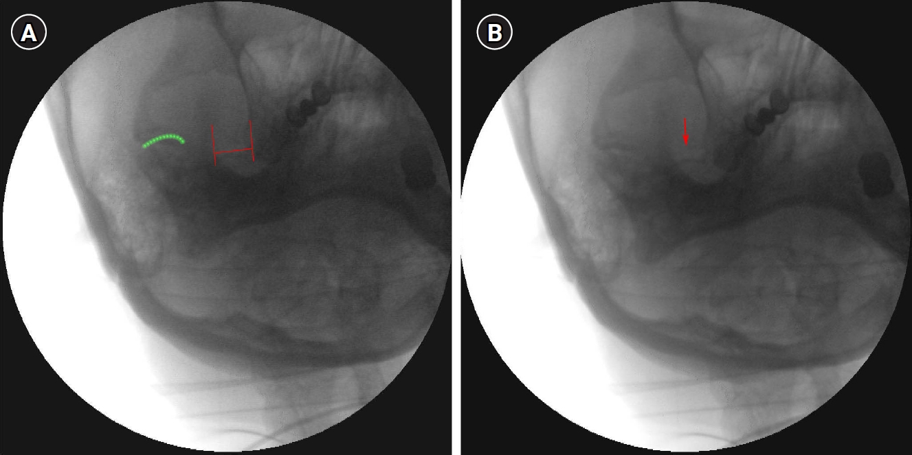
For proper visualization of FO, we used the H-figure approach suggested by He L, et al [7]. Patients were placed in supine position with their head assisted by a 10 cm pillow and their neck extended 30°- 40°. The initial C-arm axial oblique angulation was set at 20° caudally and the lateral oblique angulation was set at 15°. After the angulation, apparent H-figure could be obtained. The two vertical lines of the H-figure is the medial border of the mandible and the lateral edge of the maxilla, and the superior line of petrous ridge of temporal bone as the horizontal line (Fig 1A, B). When the H-figure was identified clearly, the lateral oblique angulation was adjusted properly so that the FO was located at the central point of the H-figure. At this position, the axial oblique rotation was adjusted to obtain the most clear and maximum view of the FO, and the C-arm images containing the best FO images were saved.
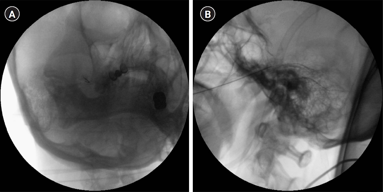
During the procedure of RFT, light sedation was maintained with intravenous midazolam at 0.02 mg/kg and sufentanil 5 μg, so that the patient could respond properly during electrical stimulation. Patient was monitored with electrocardiography, blood pressure, and pulse oximetry. Facial mask was applied to supply oxygen (3 L/min). Sterile skin draping was done at the painful side of face. Skin entry was done at 2-3 cm lateral to the angle of the mouth. A radiofrequency cannula of 22-gauge, 10-cm, and 2 mm or 5 mm active tip was used. After confirming the clear visualization of the FO, the cannula was inserted in a coaxial manner into the fluoroscopic beam towards the FO. The final depth of the needle was confirmed in a lateral view with the tip located around the clivus. Once the proper cannula position was verified with C-arm, the electrical stimulation of 0.1 V at 50 Hz frequency was in concordance with the location of the pain. The final position of the cannula tip was modified minutely, according to the effect of the stimulation (Fig 2A, B). After successful concordant electrical stimulation in the painful area, RFT was performed at 75℃ for 60 seconds for one or two times.
Analysis of fluoroscopic FO images
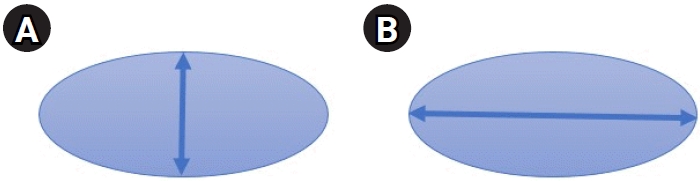
Fluoroscopic FO images that were saved during RFT were analyzed. To include the best FO images, FO images should meet two conditions; first, the position of FO should be the most central point within the H-figure. Second, the view of FO should demonstrate the maximum visualization. Maximum visualization of FO was defined according to the maximal short axis to long axis ratio of the FO. Since the FO shows round oval shape, the vertical and transverse diameter correspond to the short and long axis, respectively (Fig 3A, B). The selection of image which showed maximum visualization of FO was determined by two pain physicians who had more than 5 years experience in gasserian ganglion RFT.
To evaluate the first condition above, proper lateral oblique rotation should be adjusted. As a fluoroscopic landmark to guide a proper lateral rotation of the C-arm, the position of the medial end of TMJ was analyzed in relation to the mandibular notch when the FO was moved to the medial, central, and lateral side of the H-figure (Fig 4A-C).
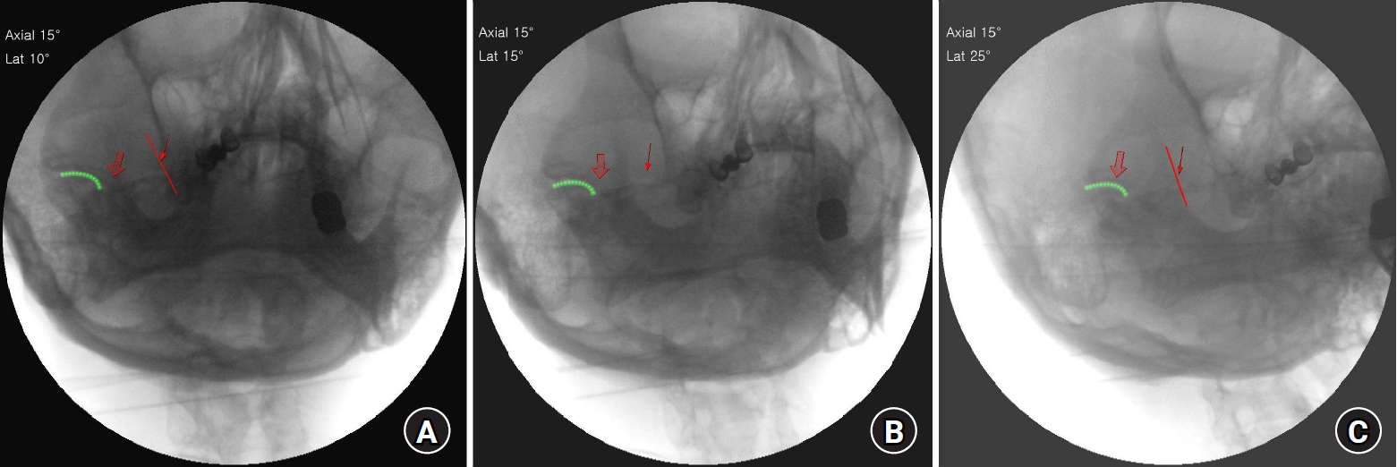
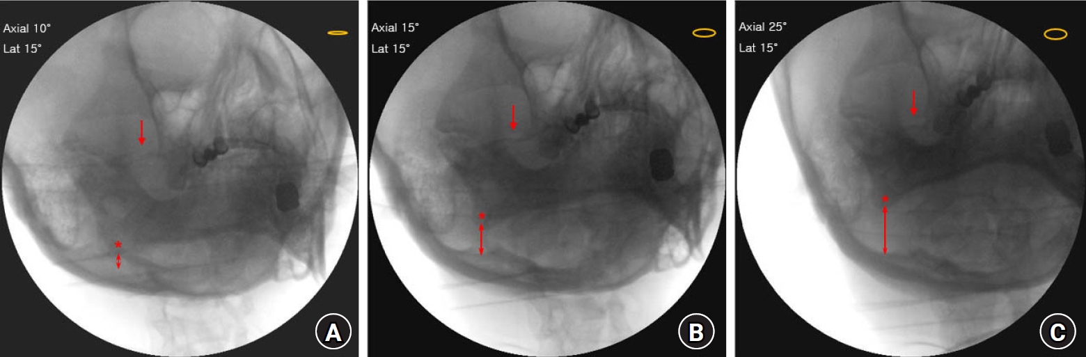
To evaluate the second condition above, proper axial oblique rotation should be adjusted. As a fluoroscopic landmark to guide an axial rotation of the C-arm, the vertical distance between the mandibular angle and the occipital inner line was measured. We analyzed the vertical distance between the mandibular angle and the occipital inner line when the FO was barely visible, better visible, and the best visible (Fig 5A-C).
All the analysis of the saved fluoroscopic FO images was performed using INFINITT PACS M6 (INFINITT Health care, Seoul, Korea).
Results
Fifty-five images of the FO, for cases that showed successful pain reduction after RFT of gasserian ganglion, were analyzed. All the 55 images demonstrated the H-figure. Among them, only 50 images of the FO met the two pre-analysis conditions; 35 female and 15 male TN patients. Fluoroscopic landmark of lateral oblique angulation
When the FO was located at the most central point within the H-figure, the medial end of TMJ was always located within the mandibular notch. All fifty images of the FO showed the medial end of TMJ located within the mandibular notch (Fig 4B). However, when the FO was too close to the medial vertical line of the H-figure, the medial end of TMJ was located to the medial point of the mandibular notch (Fig 4A). When the FO was too close to the lateral vertical line of the H-figure, the medial end of TMJ was located to the lateral point of the mandibular notch (Fig 4C). The FO was always found in the same horizontal line of the TMJ (Fig 4A-C).
Fluoroscopic landmark of axial oblique angulation
The maximum view of the FO was defined when the FO showed maximal short axis to long axis ratio. As guidance to adjust the degree of axial angulation, the vertical distance between the mandibular angle and occipital inner line was evaluated. The vertical distance between the mandibular angle and occipital inner line was widened when the axial oblique rotation was directed toward the caudal side. When the mandibular angle and occipital inner line was nearly overlapped (axial 10°), the FO was barely visible (Fig 5A). When the axial oblique rotation was directed more toward the caudal side (axial 15°), the FO was better visible (Fig 5B). When the axial oblique rotation was further directed toward the caudal side (axial 25°), the FO was best visible and the vertical distance between the mandibular angle and occipital inner line was 20.04 (5.1) mm (Fig 5C).
Discussion
The trans-oval technique is an essential step for the successful procedure of glycerol rhizolysis, balloon compression, and RFT of gasserian ganglion for the treatment of TN. Unclear visualization of the FO can lead to unwanted puncture of the other foramina at the skull base or damage of important neurovascular structure [6]. The clear identification of the FO is very important for successful procedure. However, such step was challenging and time consuming.
The H-figure method to facilitate the visualization of the FO has demonstrated an advantage in reducing fluoroscopic shots and procedure time compared to the traditional approach [7]. Previous study suggested improved visualization of the FO using CT or 3-dimensional CT reconstruction. However, such methods required higher radiation exposure to the patient and medical staff [8,10].
To adjust a proper degree of lateral and axial oblique rotation for the visualization of FO, we used a relative location of the neighboring structure. The relative location of the medial end of TMJ was used to determine the degree of lateral rotation. For the beginners of RFT, identifying joint structure might be easier than identifying the FO. Although the FO was shown up within the H-figure, one might not notice the appearance of FO. However, if the medial end of TMJ is seen within the mandibular notch, it means that the FO is present within the H-figure.
Another advantage of using the medial end of the TMJ is that the FO is always located in the same horizontal line as the TMJ. This relationship is beneficial since TMJ is a very useful fluoroscopic landmark to identify the superior line of the petrous ridge of the temporal bone [7]. If a pain physician encounters a difficulties in locating the FO, one should draw a horizontal line from the TMJ towards the medial direction and the FO could be found easily within that horizontal line.
The vertical distance between the mandibular angle and the occipital inner line was used to determine the degree of axial oblique rotation. As a novel method of locating the FO, overlapping the mandibular angle and the occipital cortical line with 15° lateral oblique rotation demonstrated clear visualization of the FO [8]. However, when the mandibular angle and the occipital cortical line was overlapped, we could barely identify the FO. The distance between the mandibular angle and occipital inner line should be widened enough, to at least 20 mm to obtain a maximum view of the FO. We thought that using the mandibular angle and occipital inner line is a practical fluoroscopic landmark since those structures are easily identifiable by the beginners of RFT.
Positioning FO within the H-figure and subsequent obtaining the best optimized view of the FO is a highly dynamic adjustment process based on the location of the neighboring structure. Optimizing the view of the FO according to a predetermined fluoroscopic angle is inaccurate since significant variations might exist among individuals [7,11].
There are some limitations to this study. First, the number of included fluoroscopic images was relatively small. Further analysis with larger numbers of fluoroscopic images is required.
Second, we evaluated the relative location of the neighboring structure of the FO in Asian people only. The fluoroscopic landmark in other racial groups might be different slightly due to different skull size. However, using a neighboring structure as a fluoroscopic landmark does not depend on fixed C-arm angulation. Rather, we suggested a practical and dynamic method to optimize the view of FO based on the neighboring structure. Third, we suggested TMJ medial end for the angulation of the lateral rotation. However, this method is hard to apply in patients who have poor fluoroscopic image of TMJ. Severe arthrosis or degenerative change of TMJ could provide poor image of TMJ.
In conclusion, the medial end of TMJ and the vertical distance between the mandibular angle and occipital inner line can be used as the fluoroscopic landmark to obtain the optimal view of the FO.